Wagner-Denoyer Projection: Introduction
I’m introducing my first own projection:
The Wagner-Denoyer projection.
Or more precisely, the Wagner-Denoyer projections because by now, there are two of them.
But we’ll cover that later.
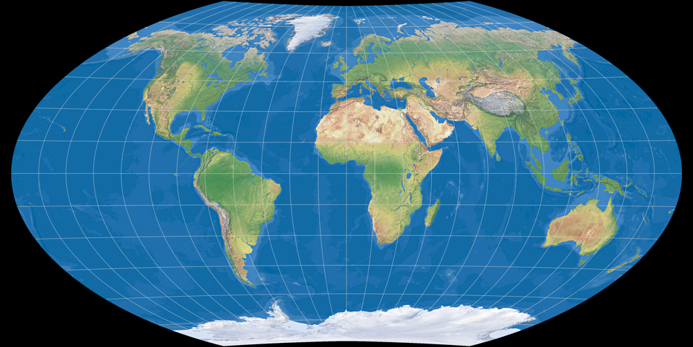
… well, calling it my own projection is quite bold. After all, it’s just a mix of Wagner VII and Denoyer Semi-elliptical that was generated using Flex Projector (see below for detailed instructions). However, I did have some things in mind when I generated this projection. So now, I’ll list them briefly, show an image of the projection. And in case you’re still interested, you can read the detailed description of my goals.
I wanted to create a projection that meets the following conditions:
- Showing the poles as line,
- not moving too far away from equivalence,
- the outer meridians shouldn’t bend too much,
- and most importantly, I wanted a decent shape for Africa as well as Greenland.
I’m fully aware that the latter three conditions are highly subjective, e.g. what I feel is a »decent shape« might look terribly distorted to someone else. But subjective matters are nothing new in the area of map projections: It was Arthur A. Robinson’s stated goal to create a map that has a pleasing appearance when he designed the projection that was named after him.
So let’s take a look at my (first) attempt.
Wagner-Denoyer I
I’m starting with the last mentioned goal.
You see, when I’m looking at a map projection, my eyes get drawn to Africa and Greenland first. (I don’t know why, but that’s just the way it is.)
Greenland is inevitably stretched horizontally if the projection has a pole line (in the equatorial aspect) and often, Africa is stretched vertically
– inevitably again in case it’s a equal-area projection.
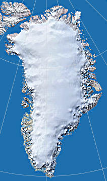
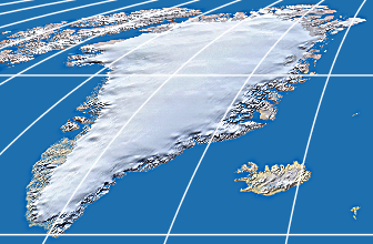
Greenland (mostly) undistorted from azimuthal equidistant projection
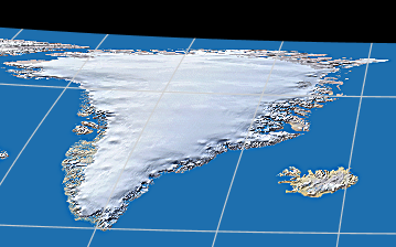
and heavily distorted
from the Wagner VII projection (equal-area)
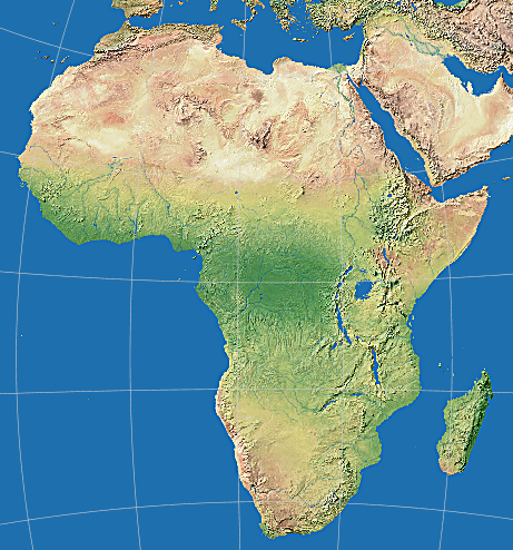
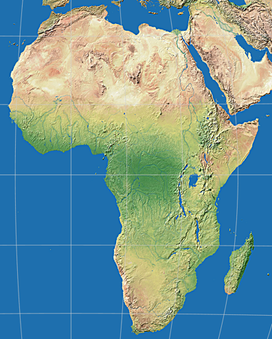
Africa (mostly) undistorted from Miller oblated projection
and visibly distorted
from the Wagner VII projection (equal-area)
What disturbs me most is the fact that Greenland’s aspect ratio is changed: While it takes a portrait orientation image to cover its real shape, you end up with a landscape orientation when you cut it from the Wagner VII projection.
Greenland (Mollweide)
But if you cut Greenland from a projection that show the poles as points… huh? The image is in landscape orientation? Right, but that’s only because of the oblique angle of its coastline, the shape itself or course still is higher than it’s wide. So this is what I was trying to achieve. Obviously, I needed a pole line that’s comparatively short.
At that point I realized that the Denoyer Semi-elliptical projection already offered some of the virtues I strived for. However, it also has a few properties I didn’t quite like: While I wanted a short pole line, it was a bit too short, I wasn’t fond of the way the meridians (especially the one close to the center meridian) converge at the poles, and I thought it wouldn’t do any harm to move it a little closer to equivalence.
So I decided to use Flex Projector to mix Denoyer Semi-elliptical with another projection. The last-mentioned thought above suggested to use an equal-area projection – and I chose Wagner VII, because it is one of my favorite equal-area projections (and, well, because Flex Projector happened to offer this projection).
The rest was done quickly:
I used Flex Projector’s Simple Mixer to blend the two projections. Then, I dragged its
Weight slider back and forth until I decided that I liked the result best if it’s set to
60% to the benefit of Denoyer Semi-elliptical.
(A detailed description of the procedure is provided below.)
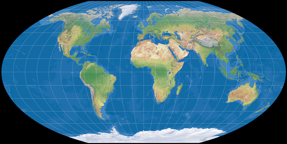
And that’s it. Here, again, Greenland and Africa compared to the undistorted variants:
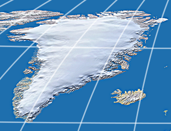
Greenland from azimuthal equidistant projection
and from the Wagner-Denoyer I projection.
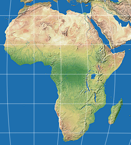
Africa from Miller oblated projection
and from the Wagner-Denoyer I projection.
Distortions, especially on Greenland, are of course still obvious. But in my opinion, it’s quite good at keeping Greenland’s appearance (i.e. being higher than wide). So, is the Wagner-Denoyer I a useful addition to the area of map projections?
Probably not.
It’s satisfying a very specific demand, which is to have what in my opinion is a pleasing appearance. And for anyone
who doesn’t share my views on aesthetics, it’s completely useless.
Well, yes, it’s the same demand that got Arthur A. Robinson started, and nowadays his projection is among the three probably
best-known projections there are (the other ones being Mercator and Winkel Tripel).
But somehow I doubt that my little experiment will be anywhere near as successful… ;-)
Construction of the Wagner-Denoyer I
In case you’d like to use the Wagner-Denoyer I in your own project, here’s how to construct it.
You will need the free application Flex Projector
(available for Linux, Mac, Windows; requires the Java Virtual Machine).
Alternatively, you can use commercial application Geocart (Mac & Windows),
which regrettably produces a little flaw. I’ll come back to that later. For now I'll just mention that you can reproduce
the steps required using the free demo version of Geocart.
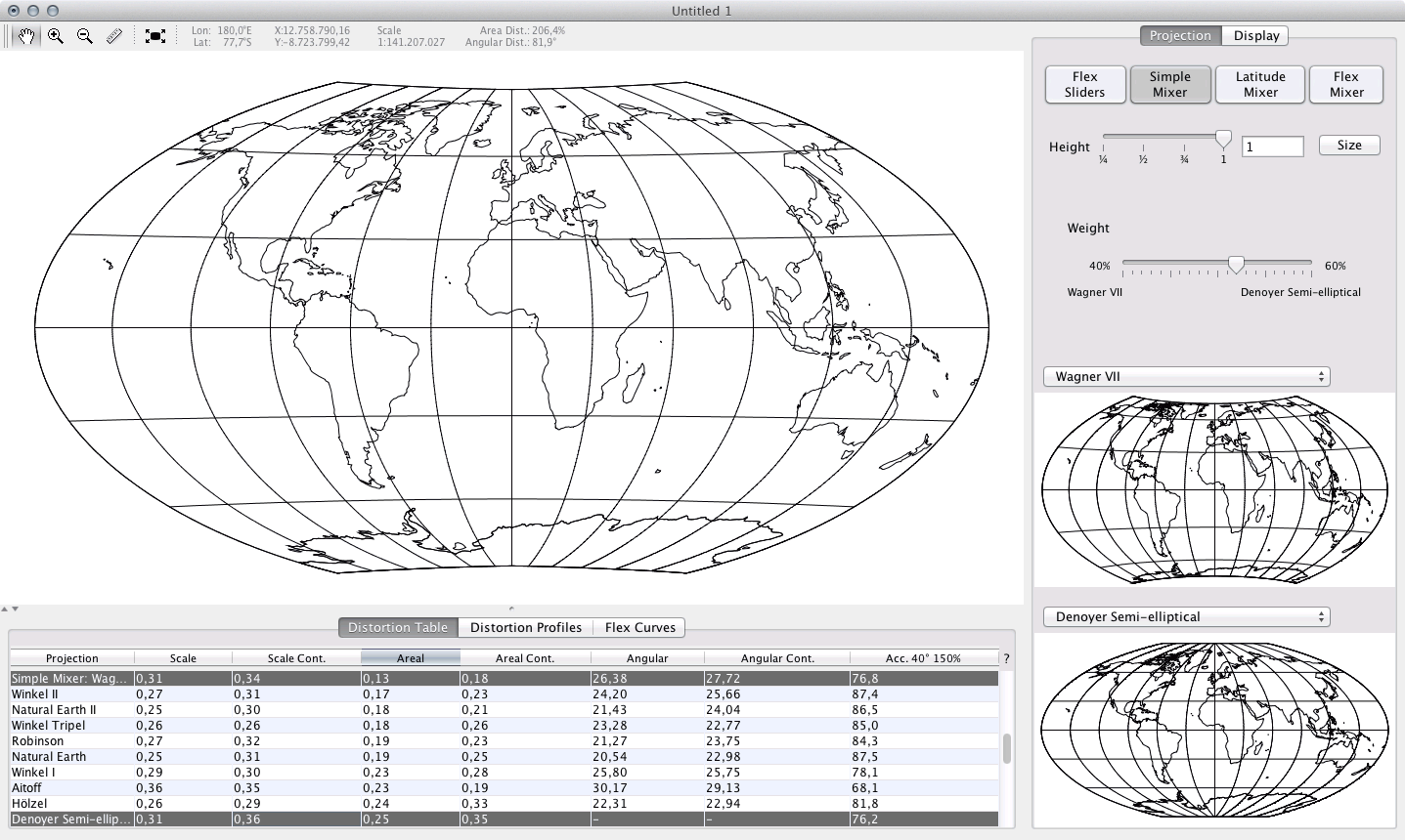
In Flex Projector, you open a new file and call up the Simple Mixer.
Select Wagner VII as first and Denoyer Semi-elliptical as second projection.
Then, move the Weight slider until it shows 60% als value for the Denoyer and (logically) 40%
for the Wagner.
That’s all.
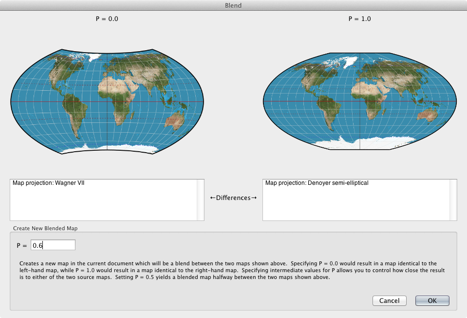
After purchasing Geocart I wanted to see if I could use this application too to generate the Wagner-Denoyer. Since it offers both projections and an option to blend two projections, the procedure was quite easy:
- Create a new file.
- Add images of the projections Wagner VII and Denoyer to your new file.
- Select both projections. From the Map menu, select New blendend…
- If in the dialogue that follows Wagner VII is shown on the left-hand side, enter P = 0.6 into the input field. In case Denoyer is left, you have to input P = 0.4 of course.
- Allow Geocart to draw the new map. After that, you can (if you wish) delete the Wagner VII and Denoyer maps from the document.
But, alas, when the task is finished you’ll notice strange ripples on the pole line:
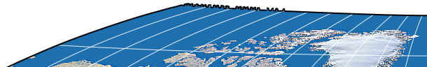
Obviously the mathematics to merge two projections having a different pole line shape aren’t that easy. I can understand this but it’s a bit of a nuisance nonetheless. After all, you can’t possibly use a map like this anywhere without post processing it using an image editor.
This brought me to the idea to try Wagner IV instead of Wagner VII because this projection has, just like the Denoyer, a straight pole line to begin with…
Wagner-Denoyer II
I composed this projection with Geocart, using the same procedure (und the same Weight value) as I’ve described above –
the only difference is that I chose Wagner IV instead of Wagner VII as parent projection.
Regrettably, Flex Projector doesn’t offer Wagner IV, but you can use my
Wagner IV approximation instead. Of course, the result won’t be
exactly the same, but close enough.
To be continued…
Sometime soon, I’m going to add a little section about the distortion characteristics of the Wagner-Denoyer projections.
Stay tuned!
Comments
Due to spam posts, comments are now subject to moderation, which means they remain hidden until they are approved by a moderator.
More info
One comment
Dr. Matthias H. Fröhlich
Triggered by news about replacement of maps with Mercator by Gall-Peters projection in Boston schools (https://www.theguardian.com/education/2017/mar/19/boston-public-schools-world-map-mercator-peters-projection) I found your site extremely well presented and achieved real insights from it. Kudos.
Best regards, Matthias